Images are representations only.
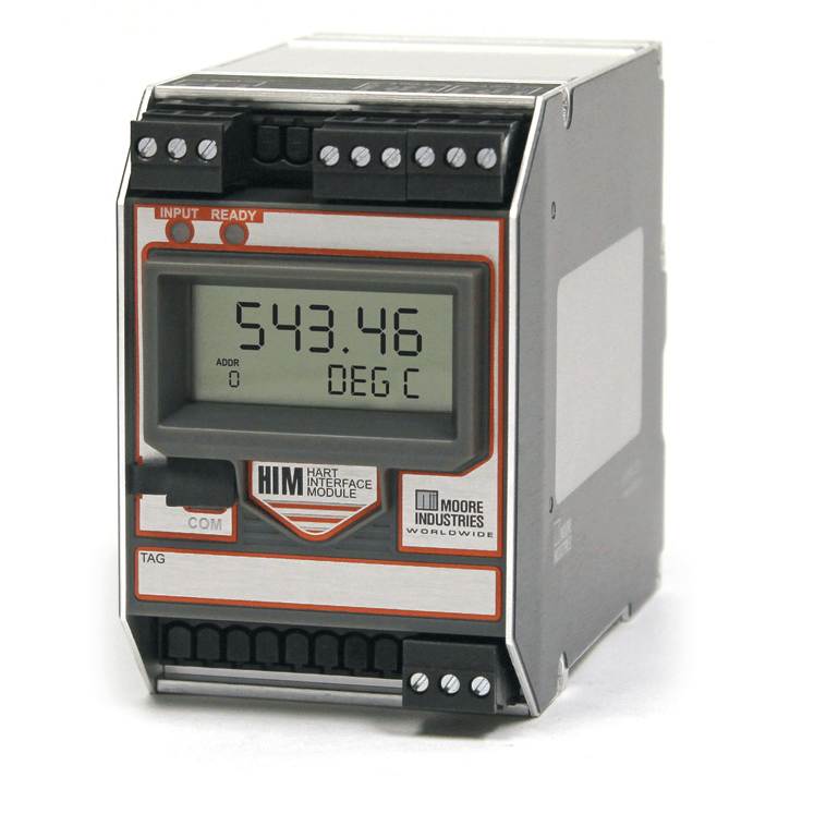
HIMHART Smart HART Loop Interface & Monitor
Brand: YokogawaThe HIMHART Loop Interface and Monitor unlocks the full potential of new and in-place smart HART multivariable transmitters and valves.
Converts HART to 4-20 mA Signals: The HIM allows up to three additional Analog process variable measurements from a smart device with no additional process penetrations or wiring.
Take Full Advantage of “Legacy” Instruments: The HIM lets you leave trusted (and paid for) smart HART transmitters and valves in place, yet still take advantage of all the information they have to offer.
Works with Every Smart HART Device: With a very simple PC program, the HIM programs in minutes to interface with every HART-compatible monitoring and control device:
- Multivariable Mass Flow Transmitters
- Dual-Sensor Temperature Transmitters
- Pressure Transmitters
- Coriolis, Magnetic, Ultrasonic and Vortex Flow Meters
- pH Transmitters
- Radar and Hydrostatic Level Transmitters
- Valve Positioners and Damper Operators
- "Break Out" up to three analog signals proportional to a HART primary, second, third or fourth variables of multivariable transmitters
- High/Low process and loop diagnostic alarms
- Normal or Burst HART Modes
- Sets up as a Primary or Secondary Master, or in "Listen" Mode
- Large, 5-digit display
- Isolated output channels
Specifications
Brand
Accuracy
- ± 0.015% of, Maximum
Alarm
- Process High/Low Alarms
Approvals & Certifications
- CE
- CSA
- EMC Directive 89/336/EEC, EN 61326
Communication
- Baud Rate: 300 to 19,200 bit/sec
- Data Length: 8-bits - Character Format
- HART
- RS-485 Modbus RTU Communication Protocol
- Start Bit: 1-bit - Character Format
- Stop Bit: 1-bit - Character Format
Consumption
- 2 to 3.5 W, Nominal
- 4.5 W at 24 Vdc, Maximum
Delay Time
- 0 to 120 seconds Programmable - Alarm Trip Delay
Diagnostics
- Process & Status High/Low Alarm
Display
- 2-Digit HART Address Indicator
- -99999 to 99999
- Bottom Row, 0.225" (6 mm) High Digits on a Reflective Background
- Large, 5-Digit Display
- Top Row, 0.4" (10 mm) High Black Digits on a Reflective Background
- Two-Line LCD Display
Electrical Connectors
- Terminal Blocks Can Accommodate 14 to 22 AWG Solid Wiring (Torque to 4 In/Lbs, Maximum
Electrical Contacts
- Normally Closed
- Normally Open
Electrical Rating
- 5 A at 250 Vac, 50/60 Hz
Environmental Protection
- Hazardous Area Class I, Division 2, Groups A, B, C, D
- Non-Incendive Apparatus Class I, Division 2, Groups A, B, C, D
Humidity
- 0 to 95% Non-Condensing - Relative Humidity
Indication
- Green Status LED of Alarm Off - TRIP 1 & 2 LED
- LED - Dual Color Red/Green Indicates Input & Ready Status
- Red Status LED of Alarm on - TRIP 1 & 2 LED
Input
- ± 5 Vdc Protection - Input Over-Range
Input Impedance
- 150 ohms - Transmit Mode
- less than 5 KiloOhms - Receive Mode
Isolation
- 1,000 Vrms between Case, Input, Outputs & Power Terminals
- 1,500 Vac Dielectric Strength Test for One Minute with No Breakdown
- 500 Vrms - Channel to Channel Isolation
Line Voltage Effect
- ± 0.005% of Output Span for a 1% Change in Line Voltage
Load
- 1,100 ohms - for Communications
- 250 ohms - for Communications
Load Effect
- ± 0.01% of Span from 0 To, Maximum
Mounting
- Surface
- Top Hat DIN Rail Mounting
Operating Temperature
- -25° to 70° C (-13° to 158° F) - Relay Range for Ambient Conditions
- -25° to 85° C (-13° to 185° F) - Display Range for Ambient Conditions
- -40° to 85° C (-40° to 185° F) - for Ambient Conditions
Output
- 0-20 mA: Fail Low to 0 mA or Fail High to 23.6 mA - Output Limits on Input Failure
- 4-20 mA: Fail Low to 3.6 mA or Fail High to 23.6 mA - Output Limits on Input Failure
- Ripple: < 10 mV peak-to-peak when Measured Across A 250 ohms Resistor
Output Noise
- 100 dB at 50/60 Hz - Common Mode for Noise Rejection
Power
- 24 Vdc ± 10%
Response Time
- < 120 milliseconds, 10 to 90% - Output Response Time
- 150 milliseconds + Digital Response Time - Alarm Response Time
- 333 milliseconds, Maximum
- 500 milliseconds, Maximum
RFI/EMI Effect
- 20 V/m at 20 to 1,000 MHz, 1 kHz AM, when Tested According to IEC 1000-4-3-1995 - RFI/EMI Immunity
- 30 V/m at 20 to 1,000 MHz, 1 kHz, when Tested According to IEC 1000-4-3-1995 - RFI/EMI Immunity
Span - Maximum
- 125% of Span Typical - Output Limiting
- 130% of Span - Output Limiting
Span - Minimum
- 1.00 - Minimum Display Span
Storage Temperature
- -25° to 70° C (-13° to 158° F) - Relay Range for Ambient Conditions
- -25° to 85° C (-13° to 185° F) - Display Range for Ambient Conditions
- -40° to 85° C (-40° to 185° F) - for Ambient Conditions
Switch Type
- DPDT Relay, 1 Form C
- SPDT Relay, 1 Form C
Temperature Effect
- ± 0.0065% of Span / °C, Maximum
Update Time
- 100 milliseconds - Display Update Rate