Images are representations only.
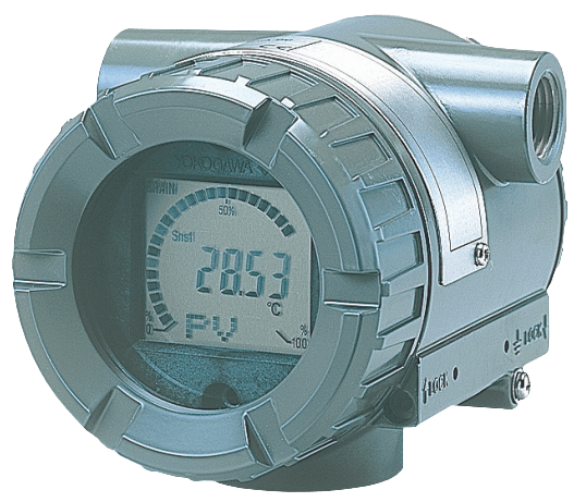
YTA310 Field Mount Temperature Transmitter
Brand: YokogawaThe YTA310 is the highly accurate temperature transmitters that accept Thermocouple, RTD, ohms or DC milivolts inputs and converts it to a 4-20 mA DC signal for transmission.
The YTA310 is a single sensor input model. The models support either BRAIN or HART communication protocol, also supports FOUNDATION fieldbus.
The YTA310 in their standard configuration, with the exception of the Fieldbus type, are certified by TÜV as complying with SIL 2 for safety requirement.
Features- Outstanding Performance
- High Reliability
- Variety of Sensor Inputs
- Digital Communication
- Self-diagnostics Function
- LCD Display with Bargraph
Specifications
Brand
Accuracy
- ± 0.02% of Span - D/A Accuracy
- ± 0.35 ohm - Resistance
- ± 0.5° C (± 0.9° F) - Cold Junction Compensation Accuracy (Thermocouple Only)
- ± 12 μV - Millivolts
Alarm
- Down-Scale: -5%, 3.2 mA DC or less
- Up-Scale: 110%, 21.6 mA DC or more
Ambient Temperature Range
- -30° to 80° C (-22° to 176° F) with Integral Indicator
- -40° to 85° C (-40° to 185° F)
Approvals & Certifications
- SIL 2 (Capability for Single Transmitter Use), SIL 3 (Capability for Dual Transmitter Use) & IEC 61508: 2000
- TUV (Technischer Uberwachungsverein)
Approvals & Certifications
- ATEX: Intrinsically Safe, Flameproof & Dust Ignition-proof
- CSA: Intrinsically Safe, Non-Incendive & Explosion-proof
- EMC: EN 61326-1 Class A (Industrial Locations), EN 61326-2-3, EN 61326-2-5 (Fieldbus)
- FM: Intrinsically Safe, Non-Incendive & Explosion-proof
- IEC Ex: Intrinsically Safe, Flameproof & Dust Ignitionproof
- NAMUR NE43 Compliant
- TIIS: Flameproof
Cable Material
- Polyethylene Insulated PVC Sheathed
Communication
- BRAIN
- FOUNDATION Fieldbus
- HART
Current
- 6,000 A - Maximum
Damping Adjustment
- 0 to 99 seconds Selectable - Damping Time Constant
Diagnostics
- Ambient Temperature Error - Self Diagnostics
- CPU Error - Self Diagnostics
- EEPROM Error - Self Diagnostics
- Loss of Input Error - Self Diagnostics
Diameter
- Cable O.D.: 0.33" to 0.43" (8.5 to 11 mm)
Display
- 5-Digit LCD - Numerical Display with °C, K, °F, °R, % & mV (Integral-Indicator)
- Bar Graph (0 to 100%) - Integral Indicator
- Dot Matrix LCD - Integral Indicator
Distance
- 0 to 2 Kilometers - Communication Distance
Electrical Connectors
- 1/2" NPT Female
- G 1/2" Female
- M20 Female
- M4 Screw Terminal
- PG13.5 Female
Electrical Protection
- Lightning Protection
Enclosure Finish
- Deep Sea Moss Green (Munsell 0.6 GY3.1/2.0) - Coating
- Epoxy Resin Coating
- Polyurethan Resin Baked Finish - Coating
Enclosure, Body Material
- SCS14A Stainless Steel (Equivalent to SUS316 Cast Stainless Steel & ASTM CF-8M)
Environmental Protection
- IP66
- IP67
- NEMA 4X
Humidity
- 5 to 100% Relative Humidity at 40° C (104° F) - Ambient Humidity Limits
Input Impedance
- 10 KiloOhms or more at 2.4 kHz - Communicating Device
Isolation
- 500 Vdc - Input/Output / Ground Isolation
Load
- 0 to 1,335 ohms - for Operation
- 0.22 µF or less - Capacitance
- 250 to 600 ohms - for Digital Communication
- 3.3 MH or less - Inductance
Materials of Construction
- 304 Stainless Steel - Data & Tag Plate, Mounting Bracket
- 316 Stainless Steel - Data & Tag Plate, Mounting Bracket
Measuring Range
- 0 to 2,000 ohms
- -10 to 100 mV
Mounting
- 2" (50.8 mm) Pipe
- M10×1.5 Female 12-Deep for Mounting Bracket
- Panel Mount (Flat)
Mounting Position
- Horizontal
- Vertical
Output
- 3.68-20.8 mA
- 4-20 mA DC - 2-Wire
Output Function
- Manually
Power Supply Effect
- ± 0.005% of Calibrated Span Per Volt
Resistance
- 1 KiloOhm or Lower - Input Signal Source Resistance (for Thermocouple, mV)
- 10 ohms Per Wire or Lower - Input Lead Wire Resistance (for RTD, ohm)
RTD Type
- Cu as Per SAMA RC21-4
- JPt100 as Per JIS C1604
- Ni120
- Pt100 as Per IEC751
- Pt200 as Per IEC751
- Pt500 as Per IEC751
Sensor Protection
- Burn-out: High (21.6 mA DC) or Low (3.6 mA DC), User Selectable
Sensor, Probe Connection
- 2-Wire RTD or ohm
- 3-Wire RTD or ohm
- 4-Wire RTD or ohm
- T/C or DC mV
Sensor, Probe Type
- B Thermocouple as Per IEC584
- E Thermocouple as Per IEC584
- J Thermocouple as Per IEC584
- K Thermocouple as Per IEC584
- L Thermocouple as Per DIN43710
- N Thermocouple as Per IEC584
- RTD
- R Thermocouple as Per IEC584
- S Thermocouple as Per IEC584
- T Thermocouple as Per IEC584
- U Thermocouple as Per DIN43710
- W3 Thermocouple as Per ASTM E988
- W5 Thermocouple as Per ASTM E988
Span - Minimum
- 10° C (18° F) - RTDs
- 20 ohms - Resistance
- 25° C (45° F) - Thermocouples
- 3 mV - DC Milivolts
Stability
- ± 0.1% of Reading or ± 0.1° C (± 0.18° F) whichever is greater for 1-Year at 23± 2° C - Thermocouples
- ± 0.1% of Reading or ± 0.1° C (± 0.18° F) whichever is greater for 2-Years at 23± 2° C - RTDs
- ± 0.2% of Reading or ± 0.2° C (± 0.36° F) whichever is greater for 5-Years at 23° ± 2° C - RTD
- ± 0.4% of Reading or ± 0.4° C (± 0.72° F) whichever is greater for 5-Years at 23± 2° C - Thermocouples
Supply Voltage
- 10.5-30 Vdc - for Intrinsically Safe, Typical N, Non-Incendive or Non-Sparking Typical
- 10.5-32 Vdc - for Lightning Protector
- 10.5-42 Vdc - for General Use & Flameproof Typical
- 16.4 Vdc Minimum - for BRAIN & HART Protocols
- 9-32 Vdc - for Fieldbus Communication Typical
Temperature Effect
- ± [0.0088% of Span + 0.007% of (Reading - LRV)]
Temperature Range
- -200° to 2,300° C (-328° to 4,172° F) - Thermocouple Measurement Range
- -200° to 850° C (-328° to 1,562° F) - RTD Measurement Range
Turn-On Time
- 5 seconds Approximately
Update Time
- Approximately 0.5 second - Single Sensor
Vibration Effect
- 10-60 Hz, 0.21 mm - Peak Displacement
- 60 to 2,000 Hz, 3 G