Images are representations only.
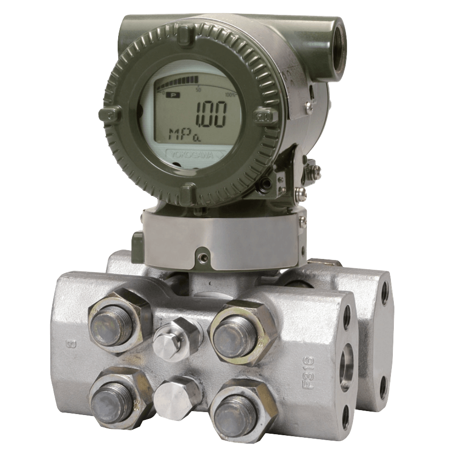
EJA440E Gauge Pressure Transmitter
Brand: YokogawaThe high performance gauge pressure transmitter EJA440E features single crystal silicon resonant sensor and is suitable to measure liquid, gas, or steam pressure. The EJA440E outputs a 4 to 20 mA DC signal corresponding to the measured pressure.
It also features quick response, remote setup and monitoring via BRAIN or HART communications and self-diagnostics. FOUNDATION Fieldbus, PROFIBUS PA and 1 to 5 V DC with HART (Low Power) protocol types are also available.
All EJA-E series models in their standard configuration, with the exception of the Fieldbus, PROFIBUS and Low Power types, are certified as complying with SIL 2 for safety requirement.
Features- Accuracy: ± 0.055% of Span
- Response Time: 90 msec
- Stability: ± 0.1% of URL per 10 years
Specifications
Brand
Accuracy
- ± (0.015 + 0.01 URL/Span)% of Span - Capsule C
- ± (0.015+0.0064 URL/Span)% of Span - Capsule D
- ± 0.055% of Span - Capsule C & D
Adjustment Type
- Push Button
- Screw - External Zero Adjustment
Alarm
- Down-Scale: -5%, 0.8 Vdc or less - for 1-5 V HART
- Down-Scale: -5%, 3.2 mA DC or less - for 4-20 mA HART/BRAIN
- Up-Scale: 110%, 21.6 mA DC or more - for 4-20 mA HART/BRAIN
- Up-Scale: 110%, 5.4 Vdc or more - for 1-5 V HART
Ambient Temperature Range
- -30° to 80° C (-22° to 176° F) - with LCD Display
- -40° to 85° C (-40° to 185° F)
Approvals & Certifications
- Leak Test
- Pressure Test
- SIL 2 Capability for Single Transmitter Use, SIL 3 Capability for Dual Transmitter Use, IEC 61508: 2000
Approvals & Certifications
- ATEX Flameproof & Intrinsically Safe
- CE
- CSA Explosion-proof & Intrinsically Safe
- EMC EN 61326-1 Class A, EN 61326-2-3, EN 61326-2-5 (For Fieldbus)
- FM Explosion-proof & Intrinsically Safe
- IECEx Intrinsically Safe & Flameproof Approval
- NAMUR NE43
- PED 2014/68/EU
Burst Pressure
- psi: 19,100 (MPa: 132, bar: 1,320)
Cable Material
- Polyethylene Insulated PVC Sheathed
Communication
- BRAIN
- FOUNDATION Fieldbus
- HART
- PROFIBUS PA
Connection Material
- 316 Stainless Steel
Consumption
- 0.96-3 mA - Power Consumption
- 27 mW - Power Consumption
Damping Adjustment
- 0 to 100 seconds
Diagnostics
- Capsule Temperature
- Configuration Error
- CPU Failure
- Hardware Failure
- Over-Range Error for Pressure
- User-configurable Process High/Low Alarm for Pressure
Diaphragm Material
- Hastelloy® C-276 - Capsule
Display
- 5-Digit Numerical Display
- 6-Digit Unit Display
- Bar Graph
- LCD Display
- User-configurable 10-Segment Signal Characterizer for 4-20 mA Output
Distance
- 0 to 2 Kilometers (1.25 Miles) - Communication Distance
Drain, Vent Valves & Plug
- 316 Stainless Steel
Electrical Connectors
- 1/2" NPT Female
- G 1/2" Female
- M20 Female
Electrical Protection
- Lightning Protection
Enclosure Finish
- Anti-Corrosion Coating
- Polyurethane Paint, Deep Sea Moss Green Paint (Munsell 0.6 GY3.1/2.0 or its Equivalent)
Enclosure, Body Material
- ASTM CF-8M Stainless Steel
- Low Copper Cast Aluminum Alloy
- Polyurethane
Environmental Protection
- IP66
- IP67
- NEMA 4X
Fill Material
- Fluorinated Oil
- Silicone
Flange Material
- F316 Stainless Steel - Cover Flange
Fluid
- Gas
- Liquid
Gasket Material
- Glass Reinforced Teflon
- Teflon-Coated 316L Stainless Steel - Capsule Gasket
Humidity
- 0 to 100% Relative Humidity - Ambient Humidity
Input Impedance
- 10 KiloOhms or more at 2.4 kHz - for Communicating Device
Length
- 1.33" (34 mm) Standard - Long Vent
- 4.6" (119 mm) - Long Vent
Load
- 0 to 1,290 ohms - for Operation
- 0.22 μF or less - Load Capacitance
- 250 to 600 ohms - for Digital Communication
- 3.3 MH or less - Load Inductance
Materials of Construction
- 304 Stainless Steel - Mounting Bracket
- 316 Stainless Steel - Name Plate & Tag, Mounting Bracket
Mounting Position
- Horizontal
- Vertical
Mounting Position Effect
- Tilting up to 90° will cause Zero Shift up to 0.4 kPa
NACE & NIST
- NACE MR-0103
- NACE MR-0175, ISO 15156
NPT Connection
- 1/2" NPT Female
- 1/4" NPT Female
Nut & Bolt Material
- 316L Stainless Steel
- 660 Stainless Steel
- B7 Carbon Steel
O-Ring Material
- Buna-N - Cover O-Ring
- Fluorinated Rubber - Cover O-Rings
Operating Temperature
- -20° to 80° C (-4° to 176° F)
Output
- 0.9-5.4 Vdc - for 1-5 V HART
- 1-5 Vdc (3 or 4-Wire)
- 3.6-21.6 mA
- 4-20 mA DC (2-Wire)
Output Load
- > 1 MegaOhm - for 1-5 V HART
Overpressure & Static Pressure Limits
- psi: 6,750 (kPa: 48,000, bar: 465.4) - Capsule C, Maximum
- psi: 8,700 (kPa: 59,980, bar: 599.8) - Capsule D, Maximum
Power Supply
- 9-28 Vdc - General Use & Flameproof Typical for 1-5 V HART
Power Supply Effect
- ± 0.005% Per Volt - from 21.6 to 32 Vdc, 350 ohms
Pressure Range
- bar: -1 to 500
- kPa: -100 to 50,000
- psi: -14.5 to 7,200
Pressure Type
- Gauge
Process Connection Material
- 316 Stainless Steel - D Capsule
- ASTM CF-8M - C Capsule
Process Temperature
- -40° to 120° C (-40° to 248° F)
Response Time
- 90 milliseconds
Screw Material
- 316 Stainless Steel
Stability
- ± 0.1% of URL Per 10-Years
Supply Pressure - Maximum
- psi: 4,500 (MPa: 32, bar: 320) - Capsule C
- psi: 7,200 (MPa: 50, bar: 500) - Capsule D
Supply Voltage
- 10.5-30 Vdc - Intrinsically Safe, Typical N or Non-Incendive Typical
- 10.5-32 Vdc - Lightning Protector
- 10.5-42 Vdc - General Use & Flameproof Typical
- 16.6 Vdc Minimum - Digital Communications, BRAIN & HART
- 24 Vdc, up to A 550 ohms Load
Temperature Effect
- ± (0.084% of Span + 0.035% of URL) Per 28° C (50° F) - Capsule C & D Ambient Temperature Effect
Update Time
- 45 milliseconds - Pressure
Vibration Effect
- <± 0.1% of URL - Tested as Per the Requirements of IEC60770-1, with Low Vibration Level (10-60 Hz, 0.15 mm Displacement / 60-500 Hz, 2 G)
- < 0.1% of URL - Tested as Per the Requirements of IEC60770-1, with High Vibration Level (10-60 Hz, 0.21 mm Displacement / 60 to 2,000 Hz, 3 G)
Wetted Materials
- 316L Stainless Steel - Capsule
- F316L Stainless Steel - Capsule
Zero Offset
- External Zero is Continuously Adjustable with 0.01% Incremental Resolution of Span
Documentation
Product Manuals
Certificate
Product Drawing
Specifications
Technical Information
- FGP-110 5 .us.pdf 717 KB
- FGP-120 4 .us.pdf 1.0 MB
- FGP-140 5 .us.pdf 813 KB
- FGP-150 4 .us.pdf 708 KB
- FGP-170 3 .us.pdf 627 KB
- FGP-210.us.pdf 584 KB
- FGP-220 2 .us.pdf 493 KB
- FGP-230 2 .us.pdf 756 KB
- FGP-250 2 .us.pdf 743 KB
- FGP-260 2 .us.pdf 658 KB
- FGP-270 2 .us.pdf 634 KB
- FGP-280 1 .us.pdf 1.1 MB
- FGP-300 1 .us.pdf 2.2 MB
- FGP-310 1st edition .us.pdf 811 KB
- TI01C25A05-01EN.pdf 658 KB
- TI01C25A05-21EN.pdf 2.6 MB