Images are representations only.
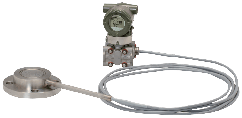
EJA438E Diaphragm Sealed Gauge Pressure Transmitter
Brand: YokogawaDiaphragm seal is used to prevent process medium form entering directly into the pressure-sensing assembly of the pressure transmitter, it is connected to the transmitter using capillary filled with fill fluid.
EJA438E Diaphragm Sealed Gauge Pressure Transmitters can be used to measure liquid, gas, or steam pressure.
EJA438E outputs a 4-20 mA DC signal corresponding to the measured pressure. It also features quick response, remote setup and monitoring via BRAIN or HART communications and self-diagnostics. FOUNDATION Fieldbus, PROFIBUS PA and 1-5 Vdc with HART (Low Power) protocol types are also available.
All EJA-E series models in their standard configuration, with the exception of the Fieldbus, PROFIBUS and Low Power types, are certified as complying with SIL 2 for safety requirement.
Features- ± 0.2% Accuracy
- 200 ms Response Time
- Exida and TUV SIL2 / SIL3 Certified
- Local Parameter Setting (LPS)
- 10-segment Signal Characterizer
- Active Capillary Fill Fluid Density Compensation
Specifications
Brand
Accuracy
- ± (0.16 + 0.004 URL/Span)% of Span (Includes Terminal-Based Linearity, Hysteresis & Repeatability) - Measurement Span A & B
- ± 0.2% of Span (Includes Terminal-Based Linearity, Hysteresis & Repeatability) - Measurement Span A & B
Alarm
- Down-Scale: -5%, 0.8 Vdc or less - for 1-5 V HART
- Down-Scale: -5%, 3.2 mA DC or less - for 4-20 mA HART/BRAIN
- Up-scale: 110%, 21.6 mA DC or more - for 4-20 mA HART/BRAIN
- Up-scale: 110%, 5.4 Vdc or more - for 1-5 V HART
Ambient Temperature Range
- -30° to 60° C (-22° to 140° F) with LCD Display
- -40° to 60° C (-40° to 140° F)
Approvals & Certifications
- Leak Test
- Material Certificate
- Pressure Test
- SIL 2 Capability for Single Transmitter Use, SIL 3 Capability for Dual Transmitter Use, IEC 61508: 2000
Approvals & Certifications
- ATEX Flameproof & Intrinsically Safe
- CSA Explosion-proof & Intrinsically Safe
- EMC EN 61326-1 Class A, EN 61326-2-3, EN 61326-2-5 (For Fieldbus)
- FM Explosion-proof & Intrinsically Safe Approval
- IEC Ex Flameproof & Intrinsically Safe
- NAMUR NE43
- PED 2014/68/EU
- PED 97/23/EC
Cable Material
- Polyethylene Insulated PVC Sheathed
Capillary Length
- 0 to 32.80 feet (0 to 10 meters)
Capillary Material
- 316 Stainless Steel
Communication
- BRAIN
- FOUNDATION Fieldbus
- HART
- PROFIBUS PA
Consumption
- 0.96-3 mA - Power
- 27 mW - Power
Current
- 6,000 A - Allowable Current
Damping Adjustment
- 0 to 100 seconds
Dead Time
- 45 milliseconds (Nominal)
Diagnostics
- Configuration Error
- CPU Failure
- Hardware Failure
- User-configurable Process High/Low Alarm for Pressure
Diaphragm Material
- 316L Stainless Steel
- Hastelloy® C-276
- Tantalum
- Titanium
Display
- 10-Segment User-configurable Signal Characterizer - for 4-20 mA Output
- 5-Digit Numerical Display
- 6-Digit Unit Display
- Bar Graph
- LCD Display
Drain, Vent Valves & Plug
- 316 Stainless Steel
Electrical Connectors
- 1/2" NPT Female - Vent/Drain Plugs
- Blind Plug
- G 1/2" Female
- M20 Female
- R 1/4" Female - Vent/Drain Plugs
Enclosure Finish
- Anti-Corrosion Coating
- Deep Sea Moss Green Paint (Munsell 0.6 GY3.1/2.0 or its Equivalent)
- Polyurethane Paint
Enclosure, Body Material
- ASTM CF-8M Stainless Steel
- Low Copper Cast Aluminum Alloy
Environmental Protection
- IP66
- IP67
- NEMA 4X
Fill Material
- Ethylene Glycol
- Fluorinated Oil
- Silicone
Flange Material
- ASTM CF-8M - Cover Flange
- JIS 304 Stainless Steel - Process Flange
- JIS 316 Stainless Steel - Process Flange, Mounting Bracket
- JIS S25C
Flange Size - 1-1/2" (DN40)
- 1-1/2" (DN40) - 150# (ANSI/JPI)
- 1-1/2" (DN40) - 300# (ANSI/JPI)
- 1-1/2" (DN40) - 600# (ANSI/JPI)
- 1-1/2" (DN40) - DIN PN 10
- 1-1/2" (DN40) - DIN PN 16
- 1-1/2" (DN40) - DIN PN 25
- 1-1/2" (DN40) - DIN PN 40
- 1-1/2" (DN40) - DIN PN 64
- 1-1/2" (DN40) - JIS 10K
- 1-1/2" (DN40) - JIS 20K
- 1-1/2" (DN40) - JIS 40K
- 1-1/2" (DN40) - JIS 63K
Flange Size - 2" (DN50)
- 2" (DN50) - 150# (ANSI/JPI)
- 2" (DN50) - 300# (ANSI/JPI)
- 2" (DN50) - 600# (ANSI/JPI)
- 2" (DN50) - DIN PN 10
- 2" (DN50) - DIN PN 16
- 2" (DN50) - DIN PN 25
- 2" (DN50) - DIN PN 40
- 2" (DN50) - DIN PN 64
- 2" (DN50) - JIS 10K
- 2" (DN50) - JIS 20K
- 2" (DN50) - JIS 40K
- 2" (DN50) - JIS 63K
Flange Size - 3" (DN80)
- 3" (DN80) - 150# (ANSI/JPI)
- 3" (DN80) - 300# (ANSI/JPI)
- 3" (DN80) - 600# (ANSI/JPI)
- 3" (DN80) - DIN PN 10
- 3" (DN80) - DIN PN 16
- 3" (DN80) - DIN PN 25
- 3" (DN80) - DIN PN 40
- 3" (DN80) - DIN PN 64
- 3" (DN80) - JIS 10K
- 3" (DN80) - JIS 20K
- 3" (DN80) - JIS 40K
- 3" (DN80) - JIS 63K
Flange Size - 4" (DN100)
- 4" (DN100) - 150# (ANSI/JPI)
- 4" (DN100) - 300# (ANSI/JPI)
- 4" (DN100) - DIN PN 10
- 4" (DN100) - DIN PN 16
- 4" (DN100) - DIN PN 25
- 4" (DN100) - DIN PN 40
- 4" (DN100) - JIS 10K
- 4" (DN100) - JIS 20K
- 4" (DN100) - JIS 40K
Flange Type
- Straight
Fluid Specific Gravity
- 0.94 to 1.92
Gasket Material
- 316 Stainless Steel (Hoop) - for Transmitter Side
- PTFE Teflon (Filler) - for Transmitter Side
Humidity
- 0 to 100% Relative Humidity - Ambient Humidity
Input Impedance
- 10 KiloOhms or more at 2.4 kHz - for Communicating Device
Load
- 0 to 1,290 ohms - for Operation - for 4-20 mA HART/BRAIN
- 0.22 μF or less - Load Capacitance
- 250 to 600 ohms for Digital Communication - for 4-20 mA HART/BRAIN
- 3.3 MH or less - Load Inductance
Load Impedance
- 550 ohms
Materials of Construction
- JIS SECC - Mounting Bracket
- JIS SUS304 Stainless Steel - Protection Tube, Mounting Bracket
- JIS SUS316 Stainless Steel - Name Plate & Tag, Mounting Bracket, Pipe
Mounting
- 2" Pipe Mounting - Transmitter
Mounting Position Effect
- Tilting up to 90° will cause Zero Shift up to 0.4 kPa
NACE & NIST
- NACE MR-0103
Nut & Bolt Material
- 316L Stainless Steel
- 660 Stainless Steel
- Carbon Steel
O-Ring Material
- Buna-N - Cover O-Ring
- Fluororubber - Cover O-Rings
Output
- 1-5 Vdc (3 or 4-Wire)
- 3.6-21.6 mA
- 4-20 mA DC (2-Wire)
Output Load
- 1 MegaOhm or Greater (Meter Input Impedance)
Power Supply
- 9-28 Vdc for General Use & Flameproof Typical - for 1-5 V HART
Power Supply Effect
- ± 0.005% Per Volt (from 21.6 to 32 Vdc, 350 ohms)
Pressure Range
- bar: -1 to 160
- kPa: -100 to 16,000
- psi: -14.5 to 2,300
Pressure Type
- Absolute
- Sealed Gauge
Process Connection Style
- Extended Typical
- Flush Typical
Process Temperature
- -50° to 310° C (-58° to 590° F)
Response Time
- 200 milliseconds (Approximately Value at Normal Temperature)
Screw Material
- 316 Stainless Steel - Zero-Adjustment Screw & Set Screws
Supply Pressure
- psi: 0 to 14.5 (kPa: 0 to 100, bar: 0 to 1) - Absolute
Supply Voltage
- 10.5-30 Vdc - Intrinsically Safe, Typical N or Non-Incendive
- 10.5-32 Vdc - Lightning Protector
- 10.5-42 Vdc - General Use & Flameproof Typical
- 16.6 Vdc Minimum - Digital Communications, BRAIN & HART
- 24 Vdc, 0 to 550 ohms Load
Temperature Effect
- ± (0.53% of Span+0.025% of URL) Per 28° C (50° F) - Ambient Temperature Effects for Capsule A & B
Update Time
- 45 milliseconds - Pressure
Wetted Materials
- 316L Stainless Steel
- Hastelloy® C-276
- JIS SUS316 Stainless Steel
- Tantalum
- Titanium
Zero Offset
- External Zero is Continuously Adjustable with 0.01% Incremental Resolution of Span - External Zero Adjustment
Documentation
Product Manuals
Certificate
Product Diagram
Specification
Technical Information
- FGP-110 5 .us.pdf 717 KB
- FGP-120 4 .us.pdf 1.0 MB
- FGP-140 5 .us.pdf 813 KB
- FGP-150 4 .us.pdf 708 KB
- FGP-160 4 .us.pdf 677 KB
- FGP-170 3 .us.pdf 627 KB
- FGP-210.us.pdf 584 KB
- FGP-220 2 .us.pdf 493 KB
- FGP-230 2 .us.pdf 756 KB
- FGP-270 2 .us.pdf 634 KB
- FGP-280 1 .us.pdf 1.1 MB
- FGP-300 1 .us.pdf 2.2 MB
- FGP-310 1st edition .us.pdf 811 KB
- FGP-340 1 .us.pdf 513 KB
- FGP-350 1 .us.pdf 451 KB
- TI01C25A05-01EN.pdf 658 KB